Computerized Necchi Supernova Prototype
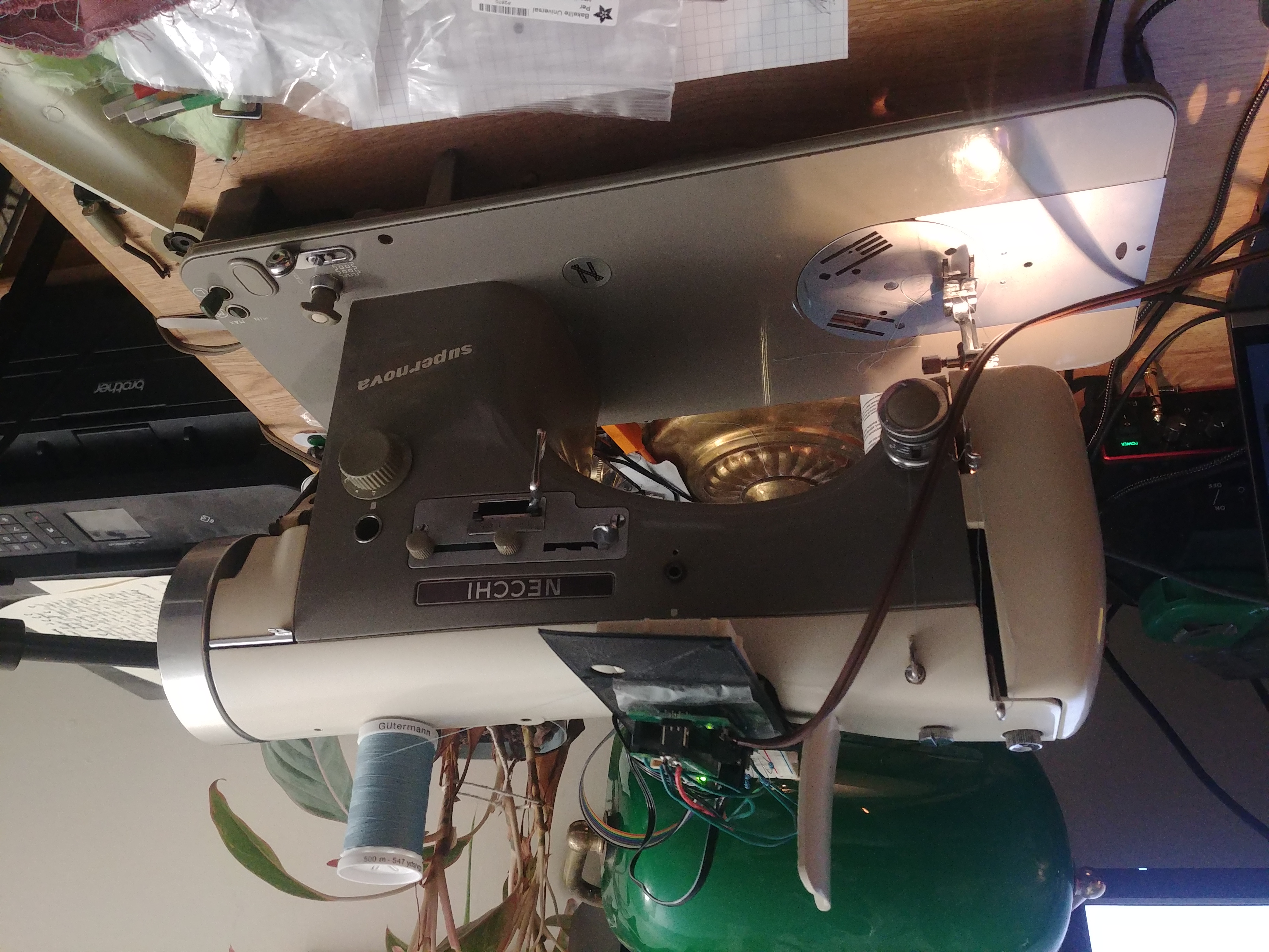
It's alive! As of last night, the computerized Necchi Supernova is working at the proof of concept level. I manually programmed some stitch patterns via servo angles, and it follows the instructions dutifully (unless I sew too fast, more on that later).
Mounting the Servo Motors
So far, most of the project has consisted of iterating on a 3D printed bracket to hold the needle position and feed dog servo motors in place. I'm on the 7th iteration now, one of which was actually a failed print that I was able to take some useful measurements from.
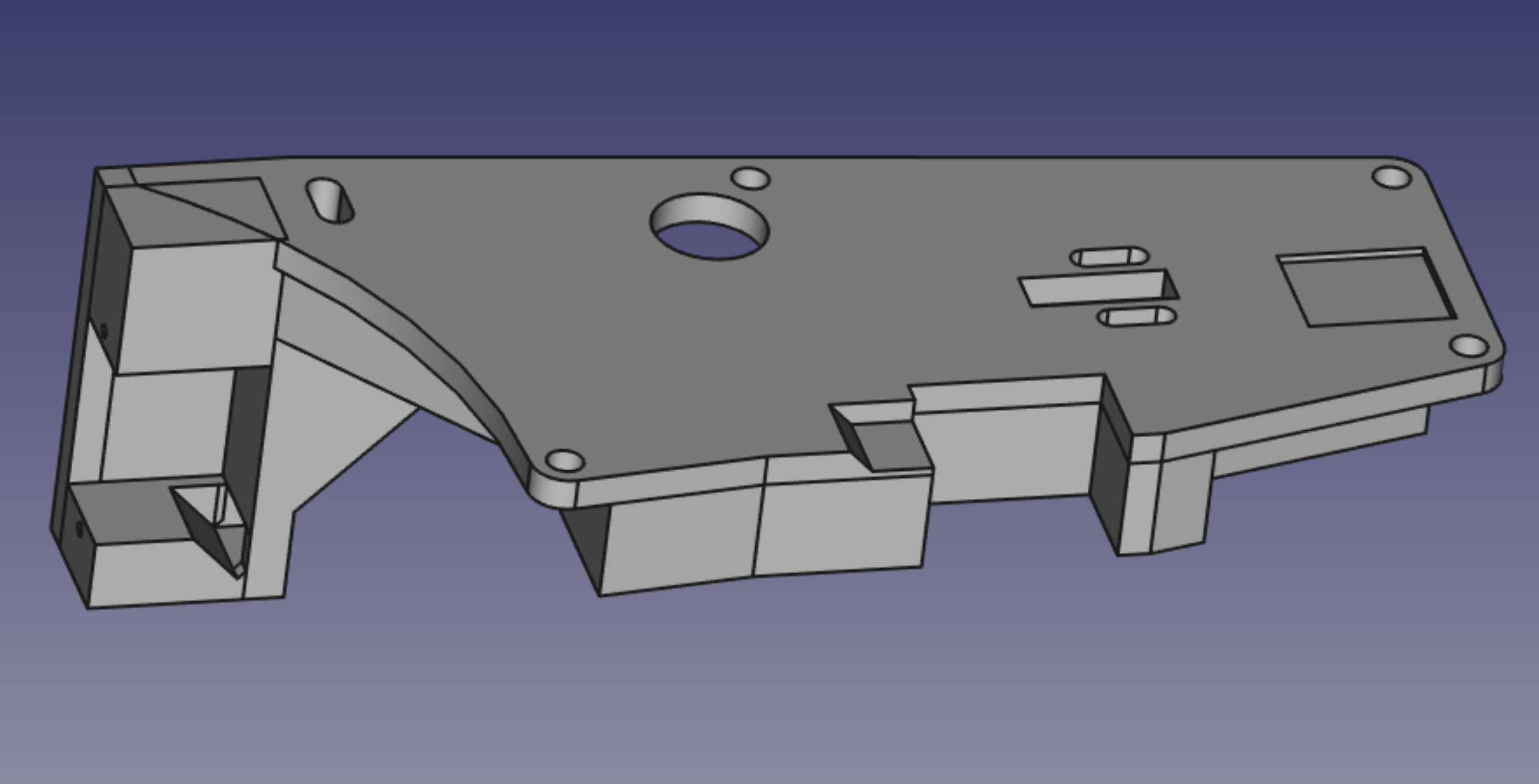
I focused first on mounting the needle position servo, being roughly centered in the screw pattern. To copy that screw pattern, I screwed a piece of paper onto the machine's top, then scanned it to take careful measurements of the resulting holes. The flatbed scanner: a hacker's best friend. Once the holes were copied, I got to work positioning the motor in a good location. This took a bit of adjustment to avoid having the servo arm or my little aluminum linkage clash with parts of the machine, but after a couple of attempts I got it all fitting. The needle position motor pushes on the same pin as the Automatica cam drive, so the external needle position lever still works as a left limit. Best to leave it on the left then!
Once that motor was fitted, I ran the machine, and noticed that the bracket was bending pretty badly under the return spring's force. A softer spring may be a good upgrade in the future, but until then, I just thickened up the bracket substantially to reduce flexing.
Keeping in mind that everything needs to be thick to be stiff, I set to work mounting the feed dog control servo. The extension to hold this servo is on the left of the render above. Still, after making things about as thick as I could, it's not as stiff as I'd like. Maybe getting an aluminum bracket made would be a good move in the future. It would also help act as a heat sink, which would be good as the motors can get fairly hot.
Making the Encoder Wheel
Next up, I needed a way to sense the machine's position. After considering my options, I decided to go for a self-made encoder wheel clamped to the machine's driveshaft, read by reflective IR sensors. Creating the encoder pattern was interesting. I timed the machine by drawing on the handwheel with a marker, then extended the marks around to the end and scanned it. The flatbed scanner: a hacker's best friend. I loaded the scan into Inkscape to copy the angles of my marks, and soon I had a little encoder pattern to print and stick on to my 3D printed clamping disk.
As for the electronics, well, that's currently the most cumbersome part of the whole project. I have a Raspberry Pi Pico with a servo shield, wired to a breadboard to read the phototransistors, all just balanced on top of the machine. This will not do in the long run, but for a first prototype, it gets the point across.
Writing Proof of Concept Firmware
There's really not much to talk about here, because MicroPython is so good for prototyping. One 25-line Python function to sense the machine's rotation and move the servos accordingly, and here we have it:
On to writing real firmware, then designing a motherboard for the machine!
⁓Clara