Computerized Necchi Supernova Planning
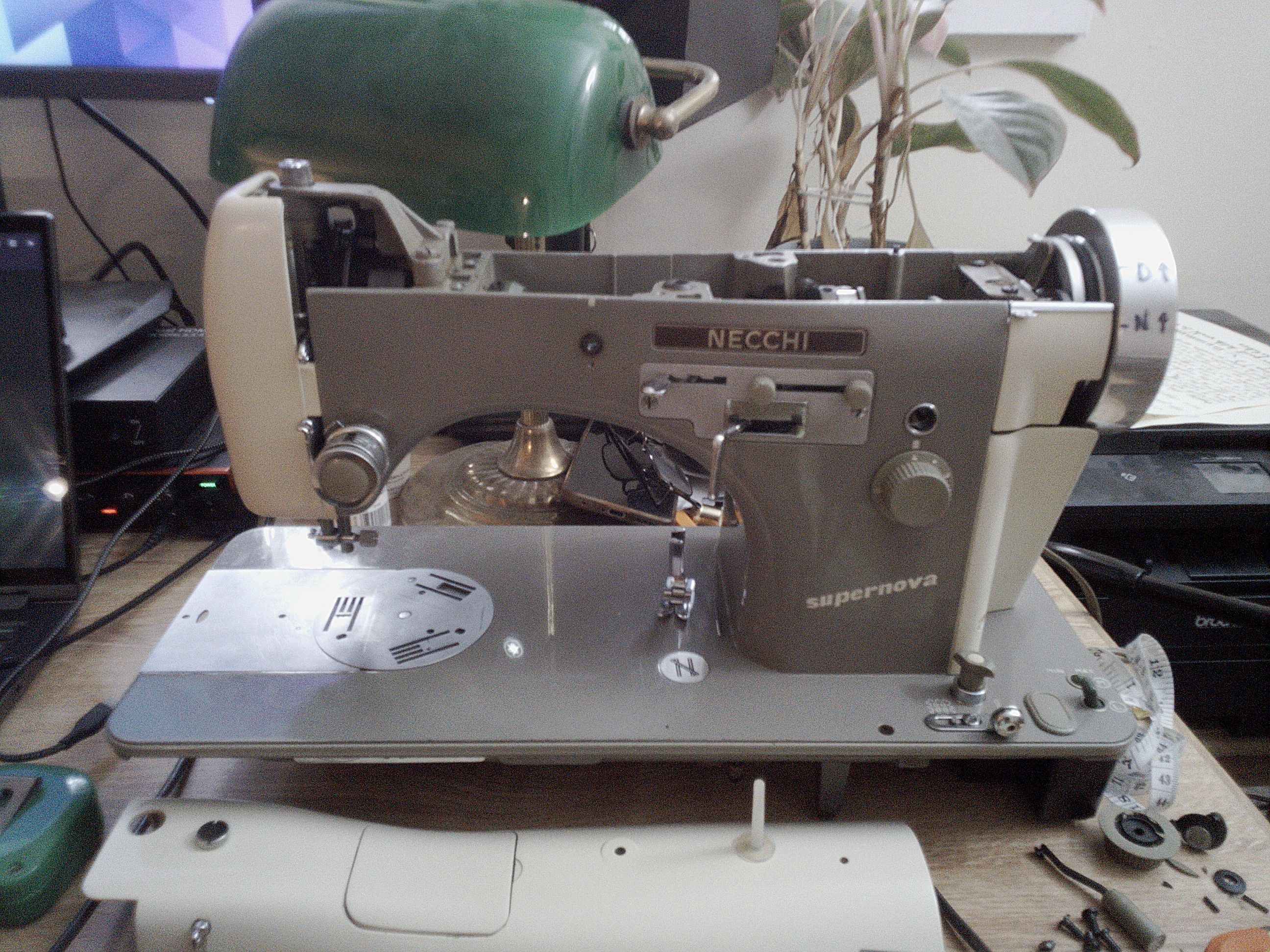
My Necchi Supernova sewing machine was sewing great up until a few days ago. But now I've gone and partially dismantled it in preparation for computerization. I took out the original embroidery unit to make space, then started planning what to do with the space inside.
I didn't take pictures while I went, so here's the current state of the machine.
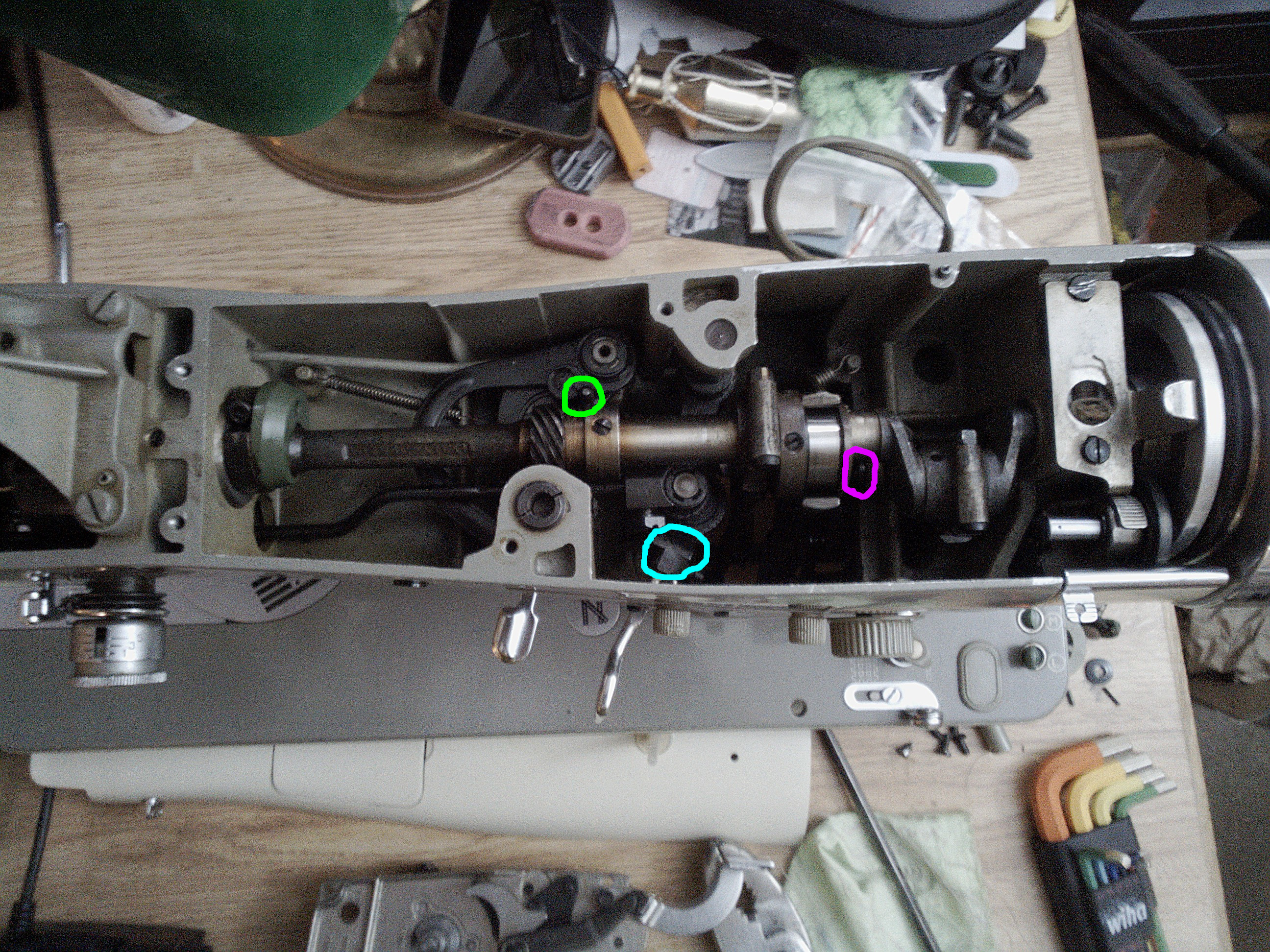
I've sloppily highlighted a few interesting points inside the machine. The post that allows me to control the needle position is circled in green. The lever for the zigzag width is circled in cyan. Lastly, the point where the reverse button connected to the feed regulator is circled in magenta. The green and magenta circles are where I plan to control the machine; the zigzag unit shouldn't be needed at all, provided I can control the needle position fast enough.
RC Servos
The plan is to cram a couple of RC servo motors inside the machine's case to link to the needle position pin and the reverse lever. The way the machine's built-in reverse button worked was actually as a continuous stitch length adjustment, going from the limit ℓ to -ℓ. Not ideal as a reverse button, but great for regulating stitch length. Just set the knob ℓ to 4 and we're off to the races. It's noteworthy that I'm opting not to link to the same lever as the original embroidery unit, as this requires too much displacement and would need more of the embroidery unit's parts. With the original reverse button removed, I should be able to fit my own pushbutton switch for computerized, instant reverse. Should be awesome if I can actually control it fast enough to make that work!
So, what are the requirements for those servos? They need to be strong enough to overcome the spring force on the feed and needle position regulators. They should ideally be fast enough to move the entire travel of their respective levers within one machine revolution. In fact, more like half of a revolution, to make sure they only move the needle and feed dogs while they're not touching the fabric. They also need to be small enough to fit inside the machine's case. Luckily, such servos can be bought, but they're not cheap. So after sinking over $100 on a pair of servos, I'm pretty confident they'll do everything I need.
Sensing Machine Position
All the mechanisms in a sewing machine are timed to a single rotating shaft. Because of this, we can check the needle and feed dog positions simply by looking at the angle of this shaft. But how can we check this? Ideally, we'd fit some kind of rotary encoder onto the shaft, but this is easier said than done. Of its two ends, one has about 1 mm of clearance to the next moving part, and the other end is the handwheel. While I could add some timing marks to the handwheel and read them with phototransistors, it would be really annoying in practice since the user would have to re-time the handwheel to the machine every time they use the bobbin winder.
The best thing I've come up with so far is to fit an encoder wheel onto the main shaft, just to the right of the green cam seen in the picture above. This can have two tracks on it: one showing when the needle is up, and one when the feed dogs are down. Then I can be sure to drive the servos only when the wheel says it's safe. I'll 3D print the disc, with a split clamp so I can screw it onto the shaft, and hopefully that'll work well enough.
Controls and Displays
As mentioned above, I removed the reverse button to make way for an electronic replacement. It'll be a light-up button, illuminated whenever the machine is moving in reverse, whether from pressing the button or otherwise.
After removing the reverse button, I attacked the embroidery unit speed knob. Literally—I didn't realize there was a roll pin holding it onto the shaft, and cracked the plastic knob pretty badly. Heed my warning if you need to remove that knob from such a machine for any reason, drive out the 1/16 in. roll pin first, then loosen the set screw and the knob should come off easily. After removing the knob, the inner part slides in to remove. I'd like to fit a rotary encoder in the knob's hole, but it's only 4 mm in diameter, smaller than most encoder shafts. So we'll see; maybe I can rig something up to fit through the hole and onto an encoder inside the case. I'd rather not drill the hole out as it has a nice press-in bushing installed, and I'd hate to lose that.
I bought a little OLED display to put inside the door for the cams. I think that would be an elegant place to put it, whether I want to keep the cover over it or not. I got a second encoder too, to eventually replace the stitch length regulating knob with. After computerization, the ℓ to -ℓ endstops won't have much of a purpose anymore, so I should be able to remove that shaft completely to simplify things, and having precise digital stitch length sounds cool.
In the long run, I might even go so far as to remove the mechanical controls for needle position and zigzag width. They won't serve much purpose if it's fully computerized, both having to be set to the left to give the servos full range of motion.
Current Status
At the moment, I'm waiting for a lot of parts to come in the mail. The servos, a driver board, a Raspberry Pi Pico (it sounds like the RP2040 is a fun chip, so why not give it a try?), and all the input and output devices I need, are all on the way. A few mechanical parts are soon to be ordered. This week, I can make the position reporting wheel. Once everything arrives, I'll have to fabricate a few linkages, which I plan to make from aluminum sheet using hand tools initially, then make better ones when I figure out exactly how long they need to be, etc. I'll need servo motor brackets as well, which I plan to 3D print, and will be interesting to model. Vague plans are starting to gel, and it's exciting!
⁓Clara